

Introducing a Pinhole
Purpose
A sequential progression from shadow casting through slit projection to pinhole imaging. Students build intuition for rectilinear propagation, image inversion, and the pinhole camera principle by drawing ray diagrams at each step.

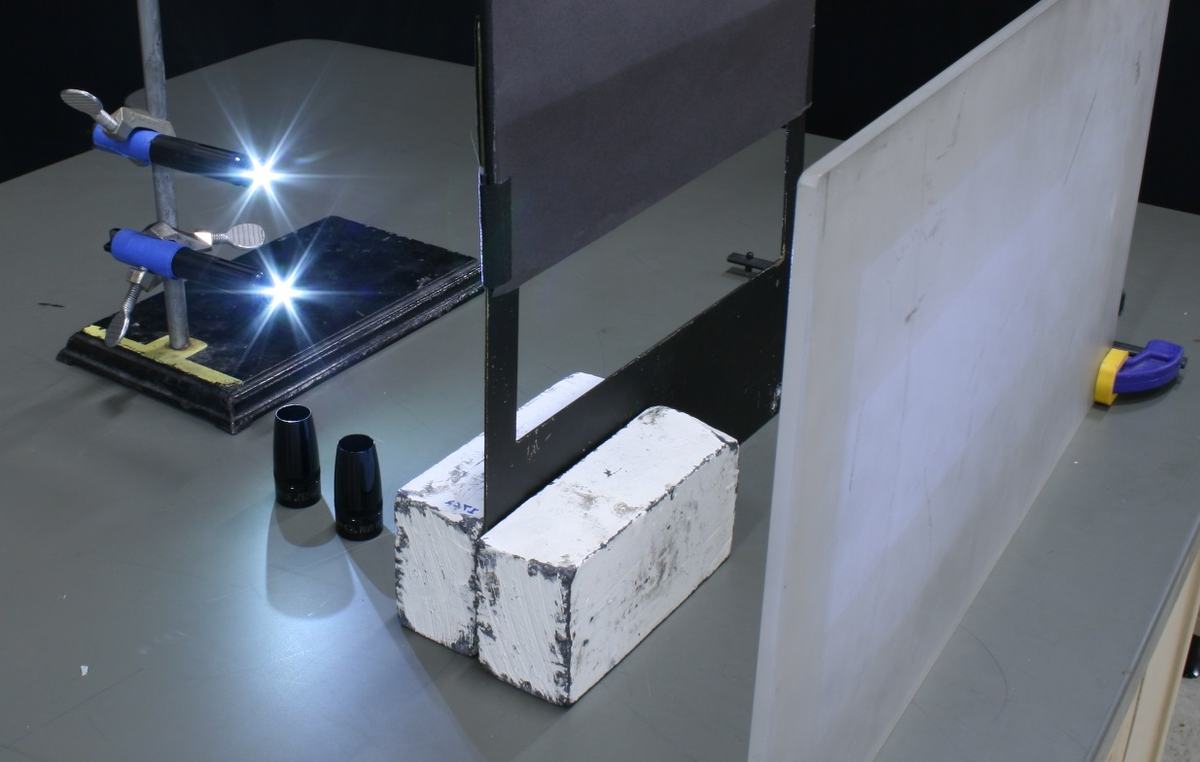
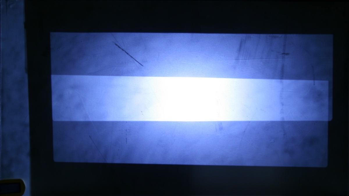
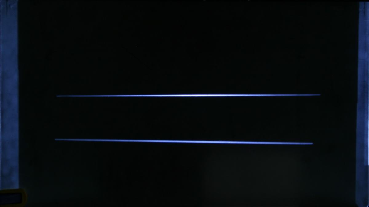

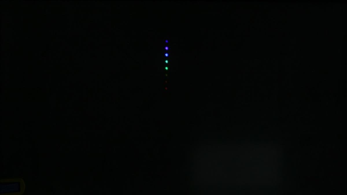

Figure 1:
Complete demonstration setup showing the translucent screen (left), LED tower for creating colored point sources, and light bulb box for demonstrating filament imaging through the pinhole.
Figure 2:
Alternate view showing the flashlight arrangement and mask positioning used in the initial shadow demonstration phase of the sequence.
Figure 3:
Screen image showing overlapping rectangular shadows from dual flashlight sources through the rectangular mask, demonstrating basic shadow formation and light blocking.
Figure 4:
Slit mask projection showing two bright lines from the dual flashlight sources, demonstrating the inverted geometry where upper flashlight creates lower line and vice versa.
Figure 5:
LED tower light passing through slit mask creating multiple colored lines, one for each LED source, demonstrating how different point sources create distinct images at different positions.
Figure 6:
Pinhole projection of LED tower showing inverted vertical array of colored dots, demonstrating true pinhole imaging where each point source creates a distinct inverted image point.
Figure 7:
Inverted image of incandescent bulb filament projected through pinhole, showing clear extended-object imaging with visible coil structure demonstrating the pinhole camera principle.
Equipment
- 1
- 1
- 1
Demo Apparatus
- 1