

Standing Waves on Rope
Purpose
A motor-driven rope stretched across the lecture bench displays standing wave patterns at resonant frequencies. Students observe nodes, antinodes, and harmonics, and see how changing tension shifts the resonance frequencies.
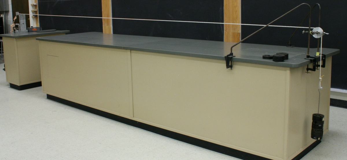
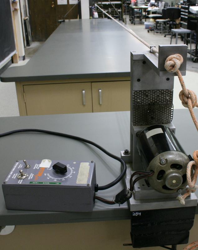

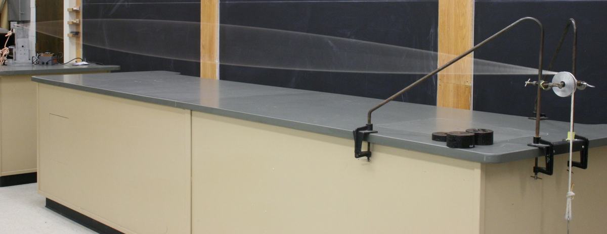


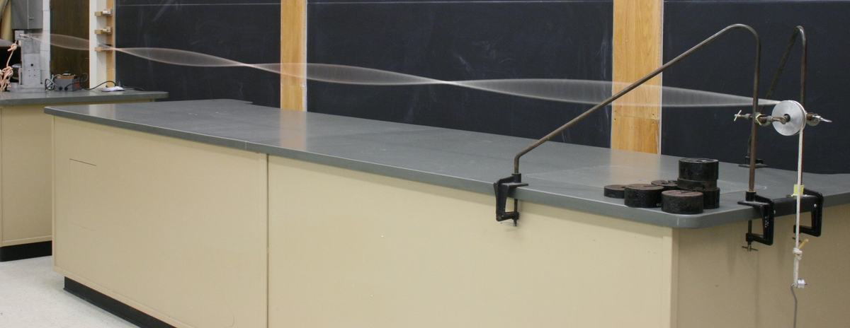

Figure 1:
Full apparatus: rope stretched across the lecture bench between the motor driver (left) and pulley with hanging mass (right).
Figure 2:
Variable speed motor driver with control box. The dial adjusts driving frequency to find different harmonic resonances.
Figure 3:
Pulley end with mass hanger providing adjustable rope tension. Changing the hanging mass shifts all resonance frequencies.
Figure 4:
Rope under tension before the motor is started, viewed from the pulley end.
Figure 5:
Standing wave with approximately three antinodes visible along the rope.
Figure 6:
Higher harmonic mode with more nodes visible along the rope length.
Figure 7:
Another harmonic mode at a different driving frequency, showing more antinodes.
Figure 8:
Strobe light used to "freeze" the rope motion, making the standing wave pattern easier to see in a darkened room.
Demo Apparatus
- 1
- 1