

LRC Demonstrator
Purpose
Demonstrate resonance in a series RLC circuit. Sweep frequency through resonance while the oscilloscope shows voltage and current becoming in-phase and current amplitude peaking when \(X_L = X_C\).
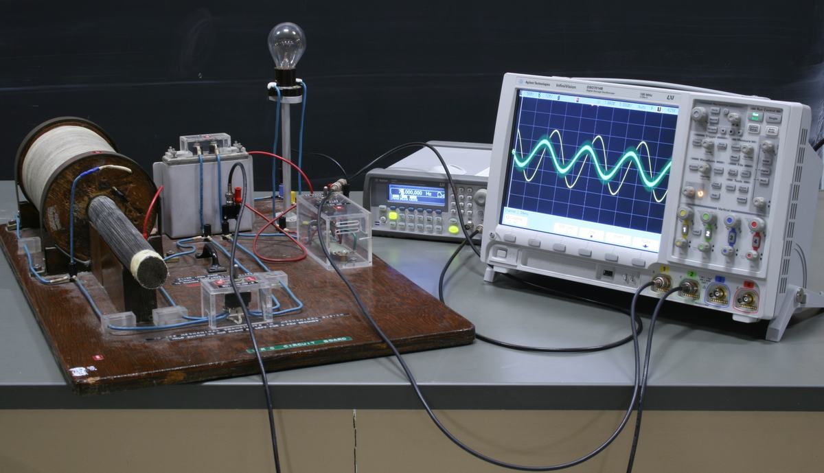
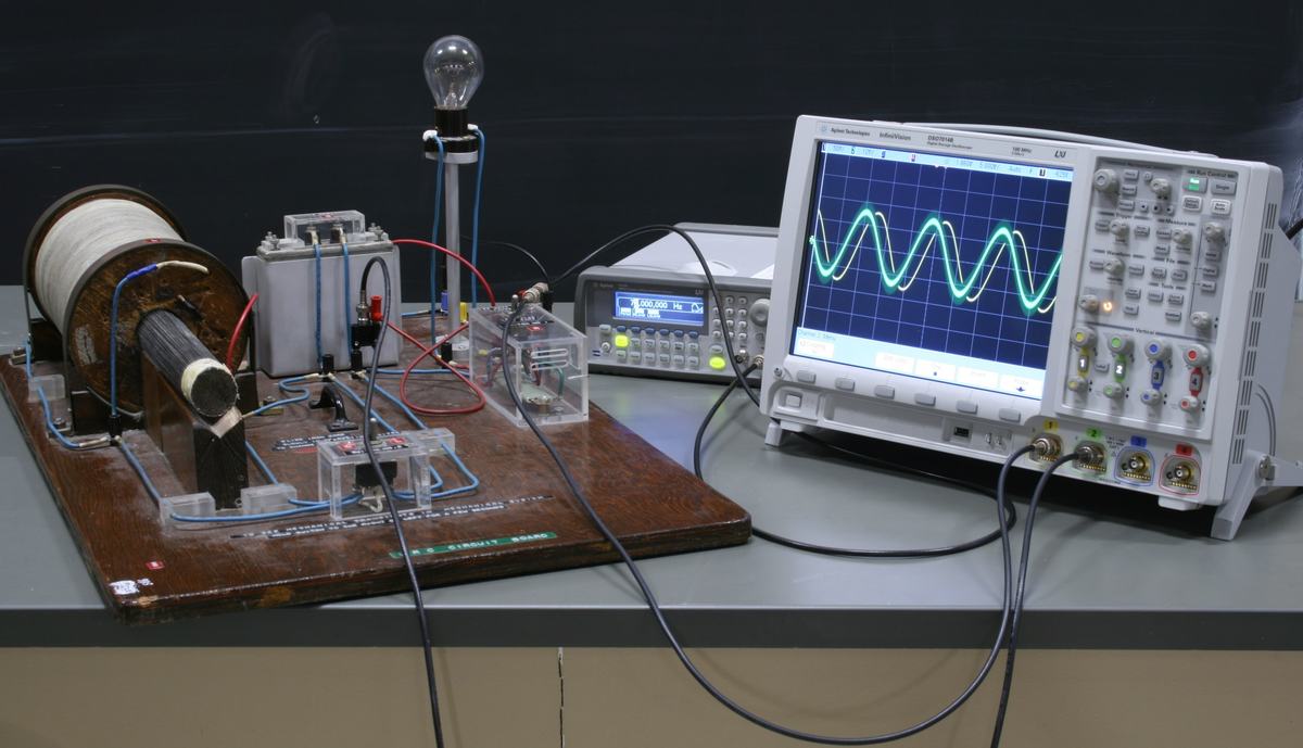
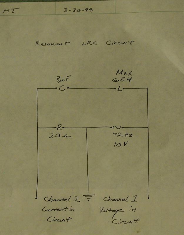
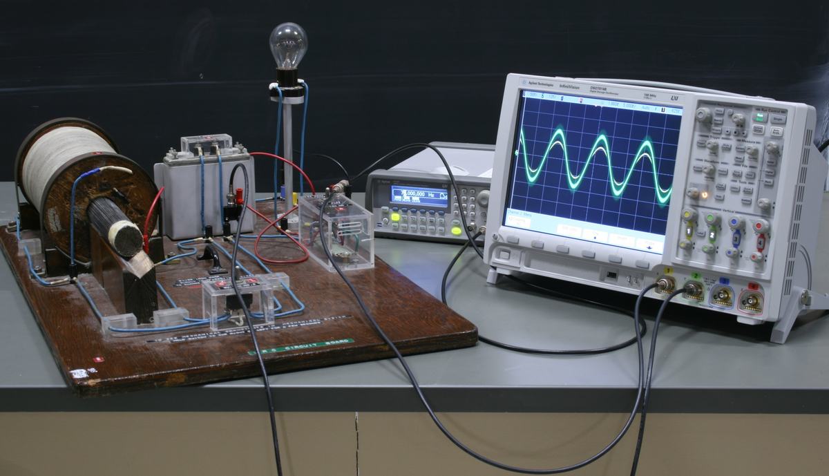

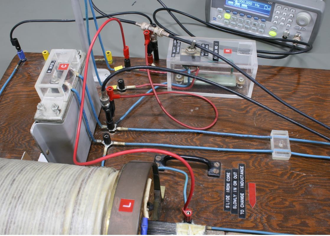
Figure 1:
Complete setup: LCR board with wire spool inductor, light bulb indicator, function generator, and oscilloscope displaying voltage and current waveforms.
Figure 2:
Off-resonance: visible phase difference between voltage and current traces on the oscilloscope.
Figure 3:
Handwritten schematic: C = 8 μF, L = 6.5 H (max), R = 20 Ω, driven at 72 Hz / 10 V. Ch 1 measures voltage, Ch 2 measures current.
Figure 4:
Near resonance: voltage and current traces are nearly in phase, and current amplitude is at maximum.
Figure 5:
Off-resonance: significant phase shift between voltage and current. Capacitive or inductive reactance dominates.
Figure 6:
Close-up of the LCR board. Transparent enclosures show component construction. The inductor has a sliding knob to adjust inductance.
Demo Apparatus
- 1