

Time Constant of RC Circuit
Purpose
Visualizes exponential charging and discharging of a capacitor driven by a square wave. Students observe the characteristic RC exponential curves on an oscilloscope and see how \(\tau = RC\) governs the response time.
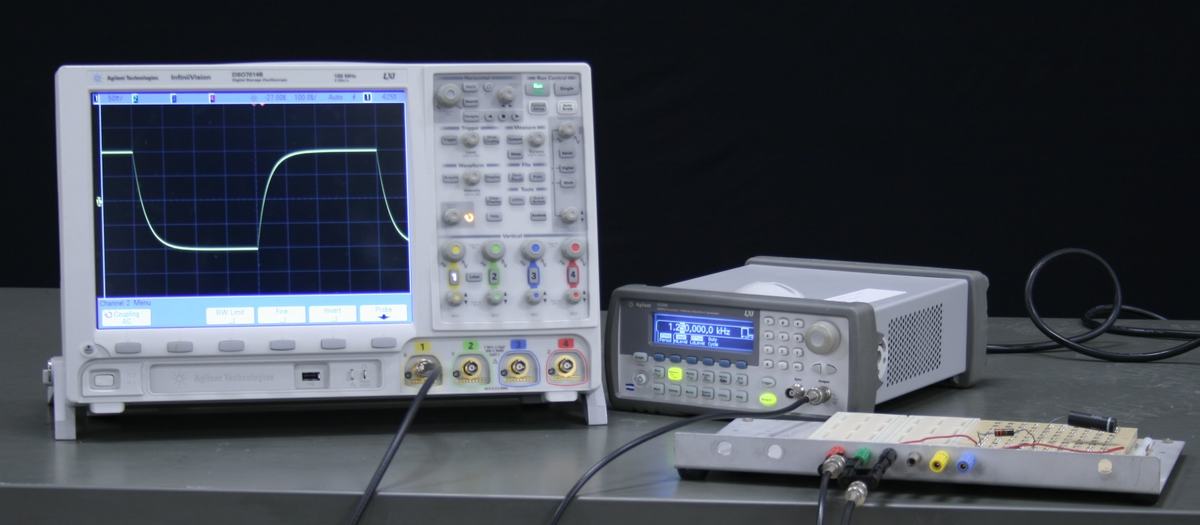
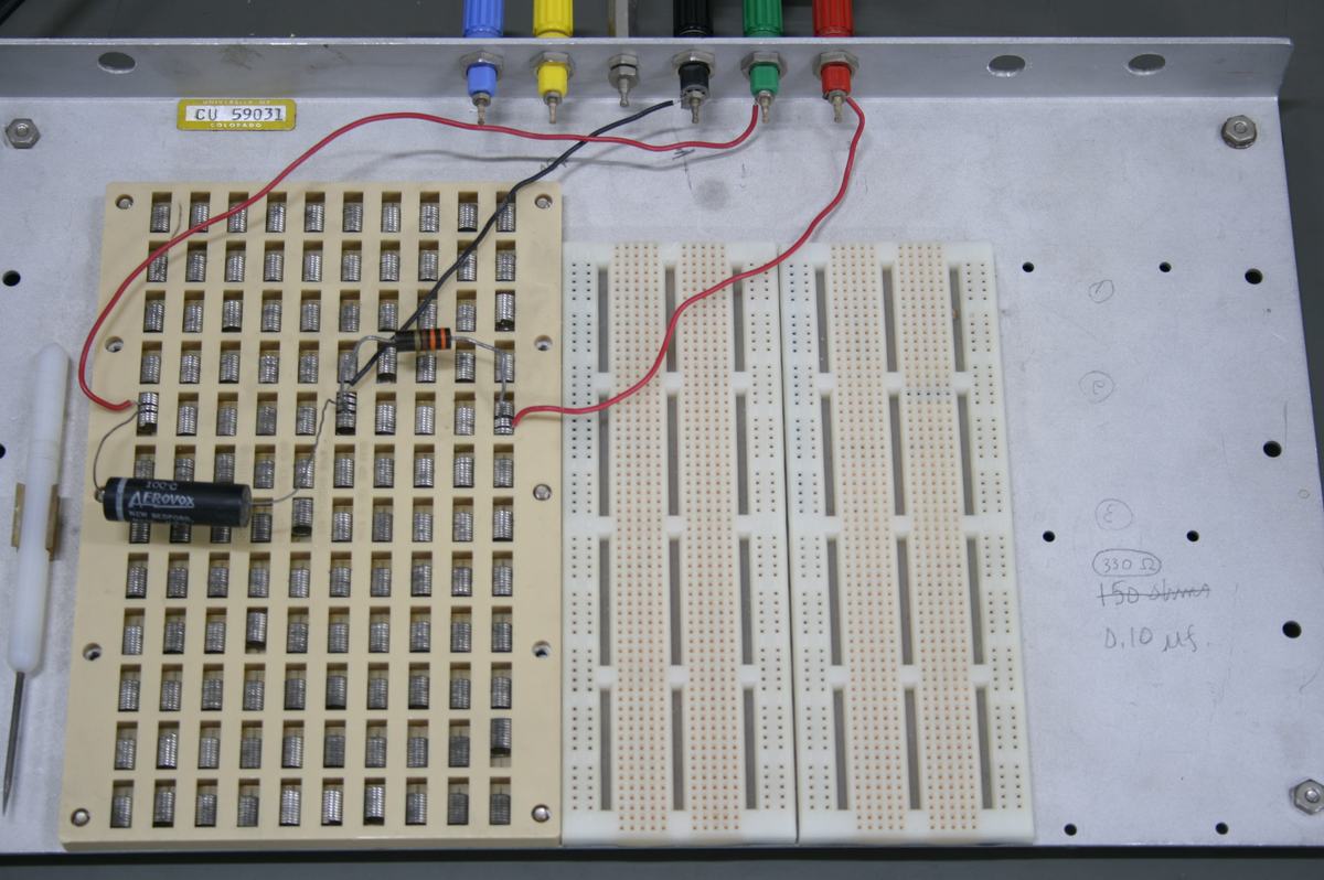
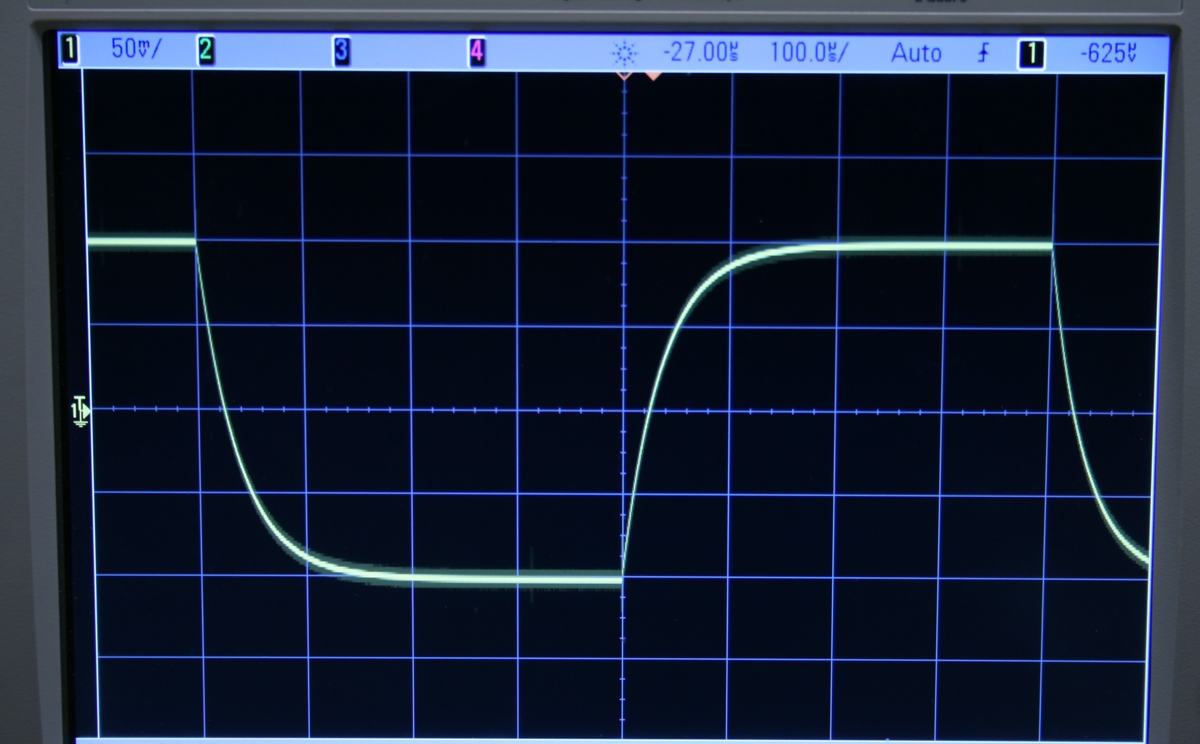
Figure 1:
Complete setup: oscilloscope shows the input square wave (upper trace) and capacitor voltage with exponential charging/discharging (lower trace), with function generator and breadboard RC circuit.
Figure 2:
The RC circuit breadboard with resistor and capacitor. Handwritten label indicates R = 330 Ω and τ ≈ 0.10 μs.
Figure 3:
Close-up of oscilloscope traces showing the input square wave and the capacitor voltage with characteristic exponential charging and discharging curves.