

Magnetic Slides
Purpose
Iron filings in a sealed projectual reveal magnetic field line patterns around various bar magnet configurations. Students observe how field geometry depends on magnet arrangement and how field line density reflects field strength, reinforcing superposition and the dipole nature of magnets.
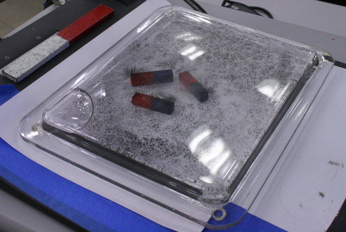
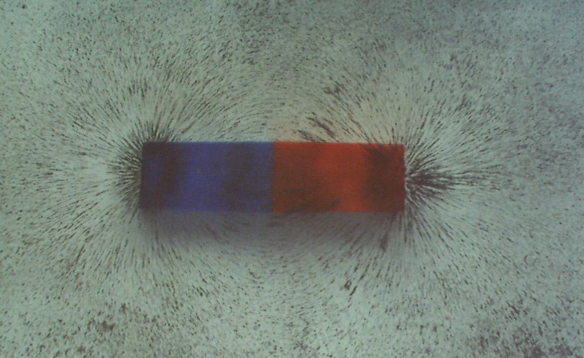
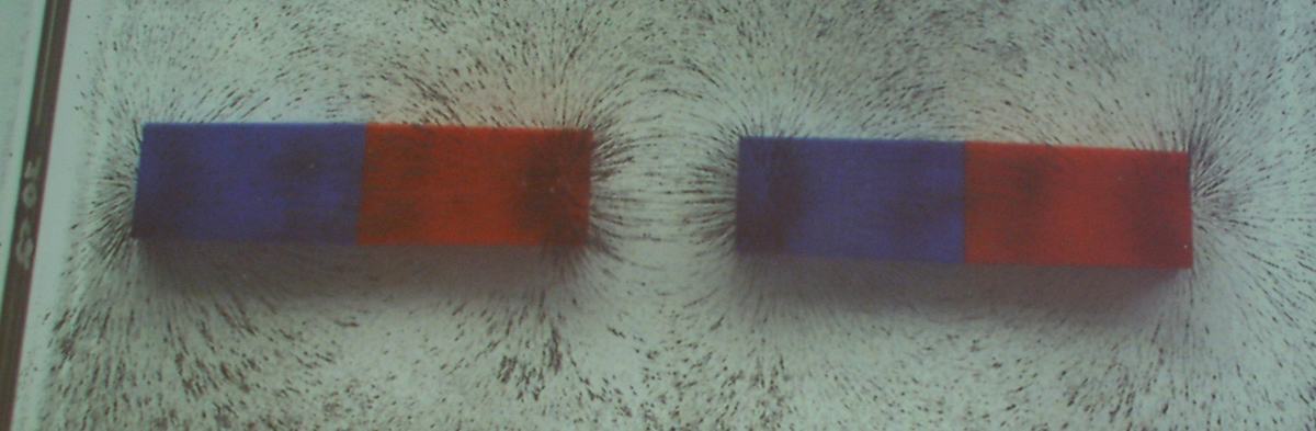
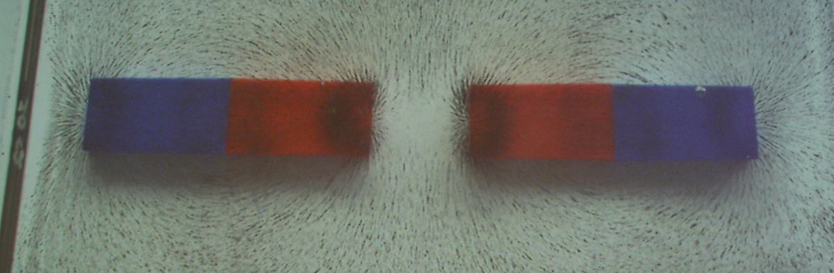
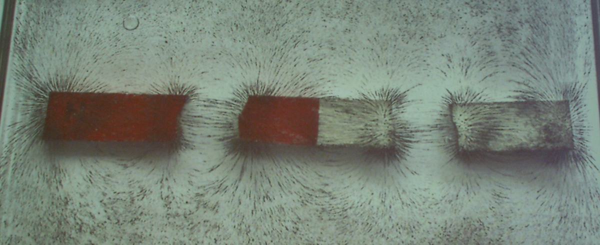
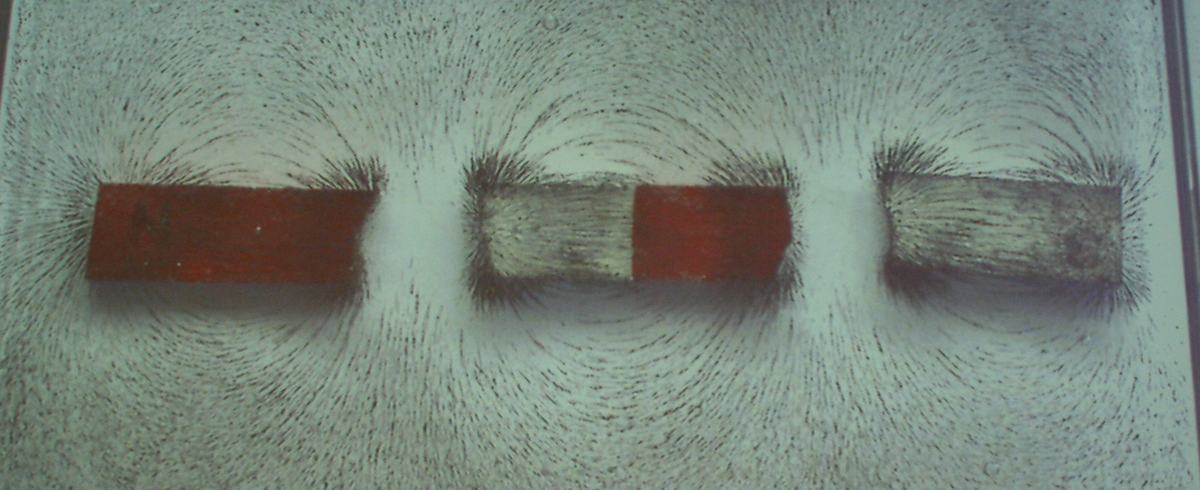
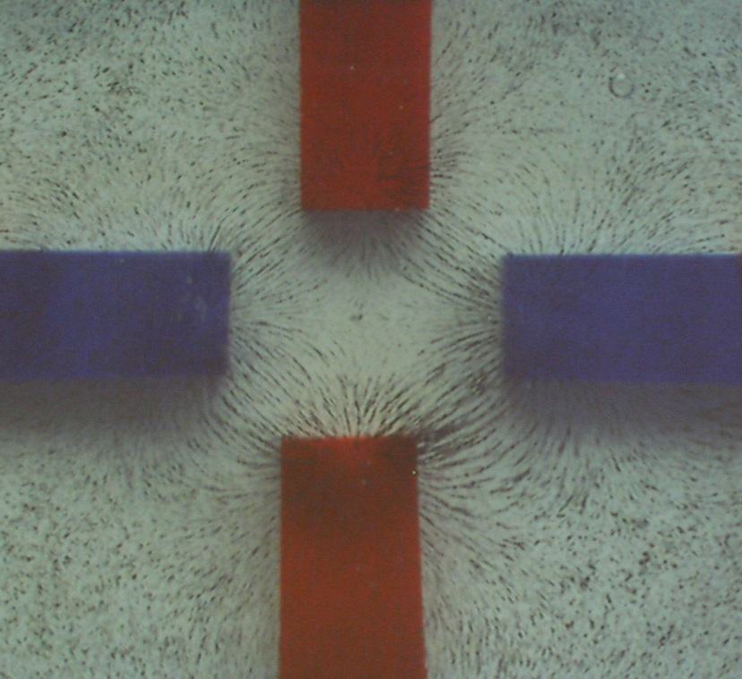
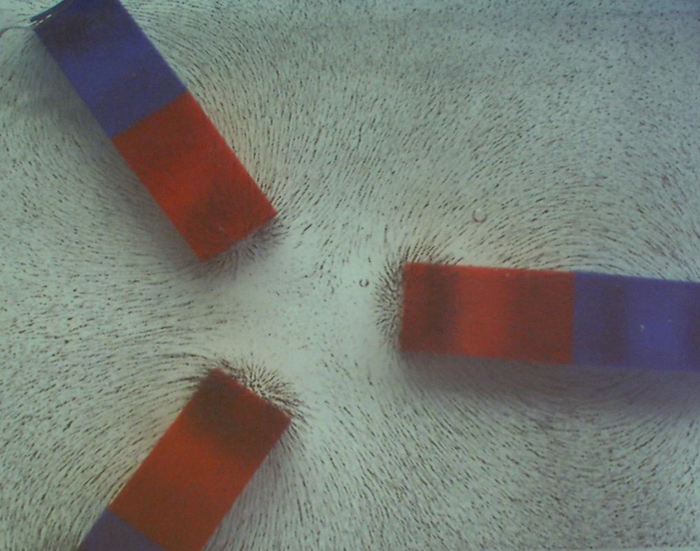
Figure 1:
The magnetic field projectual with iron filings distributed to show field patterns around multiple bar magnets. The tray includes a glass stirring rod for resetting the filings between demonstrations.
Figure 2:
Classic dipole field pattern of a single bar magnet. Field lines emerge from the red (north) pole and curve back to the blue (south) pole, with highest density near the poles.
Figure 3:
Field pattern showing attraction between opposite poles (north-south configuration). Field lines connect directly between adjacent poles, demonstrating field superposition.
Figure 4:
Repulsive configuration with like poles adjacent. Field lines curve away from the central gap, clearly showing the absence of field line connection between like poles.
Figure 5:
Multiple identical magnets demonstrating field superposition. The complex pattern results from vector addition of individual magnetic fields.
Figure 6:
Cross configuration showing how magnetic fields interact in two dimensions. The central region shows complex field structure from four-way superposition.
Figure 7:
Two magnets at angles showing how field patterns depend on relative orientation, not just distance.
Figure 8:
Arbitrary configuration useful for discussing field mapping techniques and reinforcing that magnetic fields exist continuously in space, not just along symmetry axes.