

EQE Apparatus Guide
1 Overview
This lab guide will walk you through the process of using the EQE apparatus. The process is split into three parts: Setup, Data Collection, and Experiment Wrap-up.
2 Apparatus Components
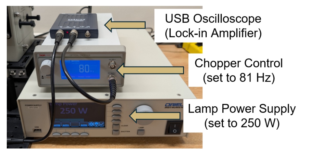
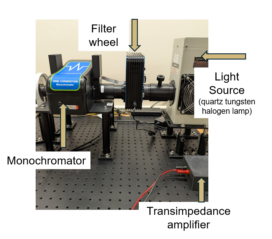
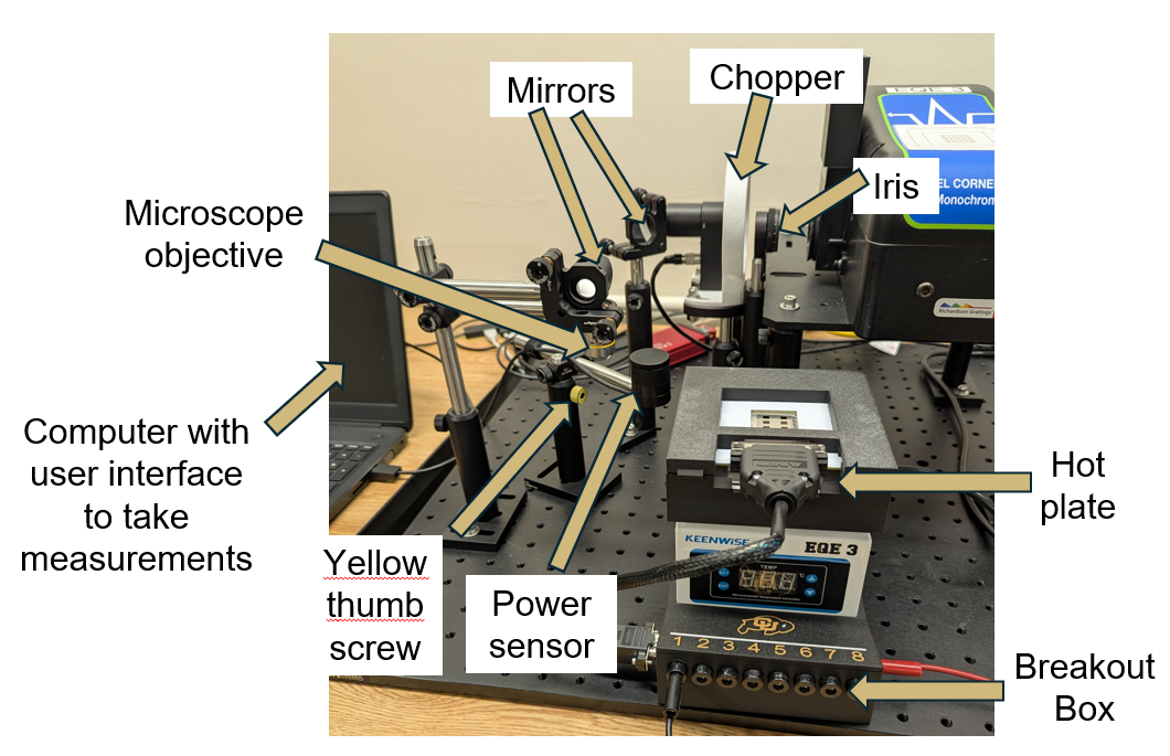
3 Setup
This portion of the lab guide covers the steps for setting up your solar cell to take EQE measurements.
Make sure the room lights over the EQE apparatus are turned off.
Collect your cell from the stressing room and record the time you took it off the station.
Without delay, open the lid on the hot plate and place your cell inside the alignment jig. The cell pixel mask should be visible from the top, as shown in Figure 4.
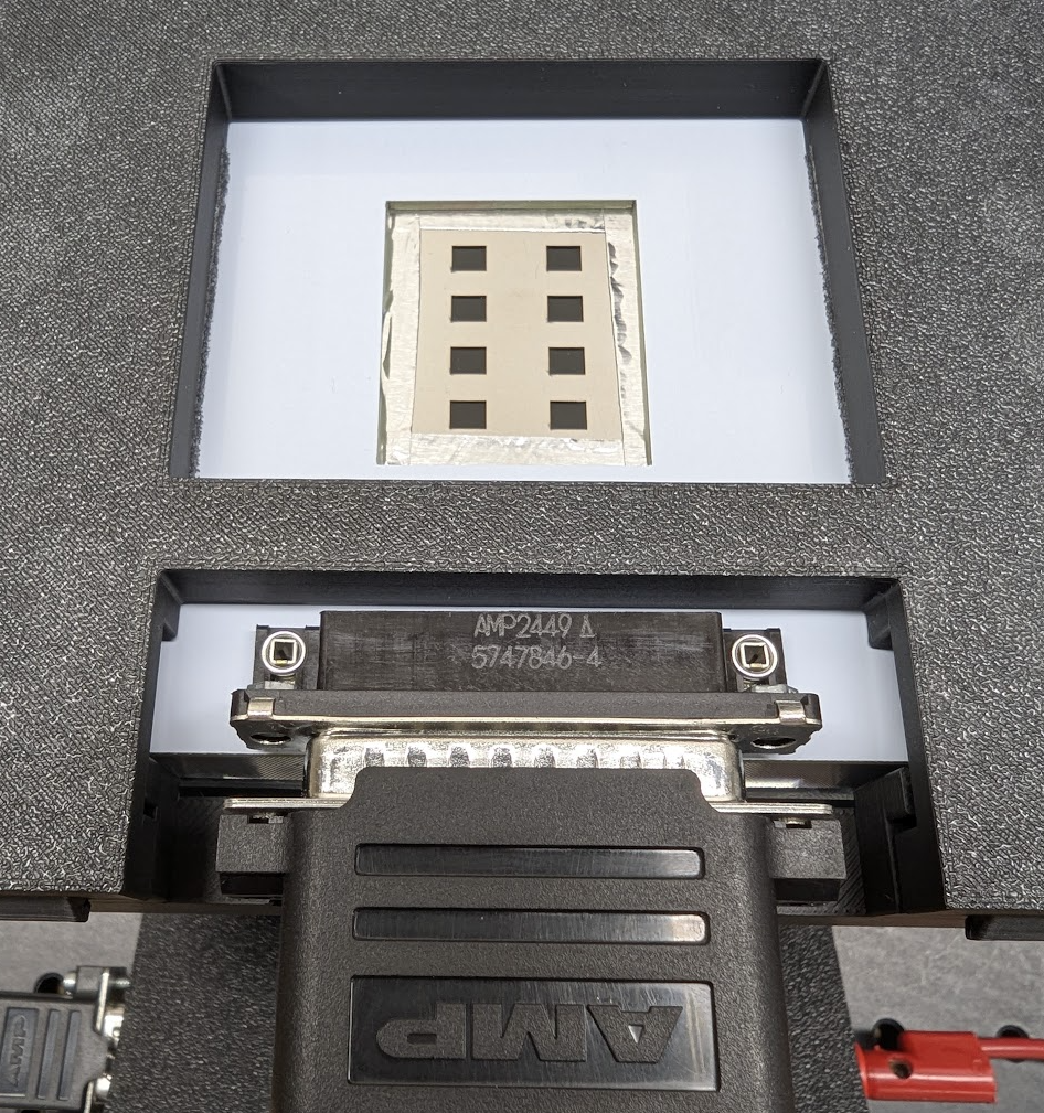
Figure 4: Cell in alignment jig Snap the lid closed.
Plug in the 25-pin connector from the breakout box into the cell.
Let your cell sit on the hot plate for 5 minutes to reach the testing temperature. Set a timer!
While you are waiting for your cell to equilibrate, log into the laptop using your IdentiKey, open a web browser, and log into your team’s Google Drive. Set up a folder for this week’s measurements.
Open the “PHYS 2150 Measurement Suite” app on the Desktop and select “EQE Measurement” (or press “E” on your keyboard). When prompted, enter your cell number and click Continue.
Make sure the banana plugs of the black and red leads are plugged into the appropriate banana sockets. The red lead should be plugged into the red banana socket — it will remain here for all of your measurements. The black lead should be plugged into the Pixel 1 banana socket. This lead will be moved as you do measurements for different pixels. Your starting setup should look like Figure 5.
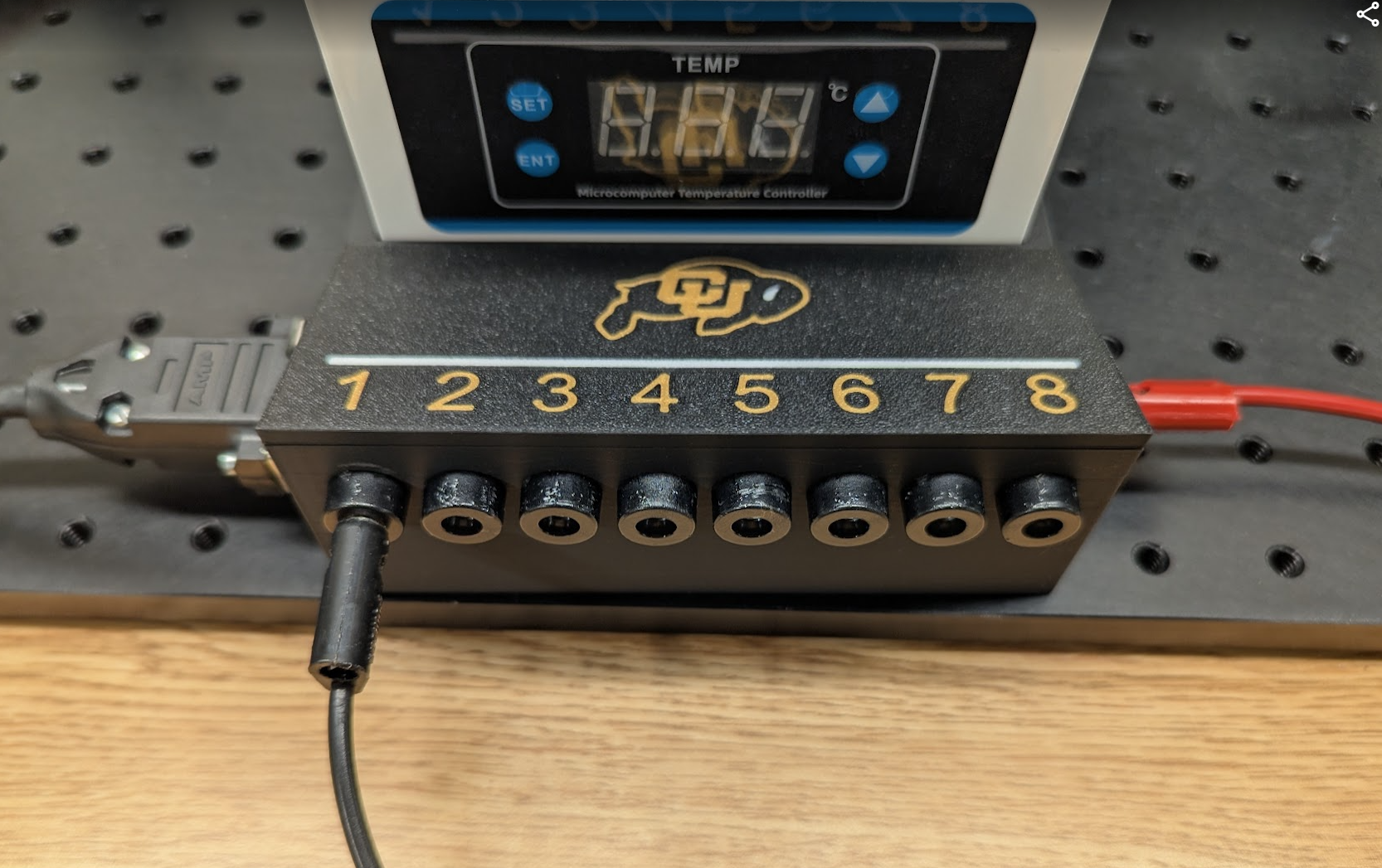
Figure 5: EQE breakout box
Once your 5 minute timer has gone off, you are ready to move on to data collection.
4 Data Collection
This portion of the guide covers the steps for collecting the EQE measurements for each pixel of your solar cell. All of your measurements will be taken through the PHYS 2150 Measurement Suite app. Enter your cell number into the pop-up window that appears after the app launches. The default settings for the start, end, or step wavelengths should be left as-is (unless the instructor or TA communicates a necessary change).
4.1 Power Measurement
Unscrew the cap on the Photodiode Power Sensor.
Loosen the yellow thumb screw on the post holder to lower the power sensor.
Slide the power sensor under the microscope objective and readjust the height so the power sensor lens tube sits just below the yellow ring on the microscope objective, then tighten the yellow thumb screw (see Figure 6).
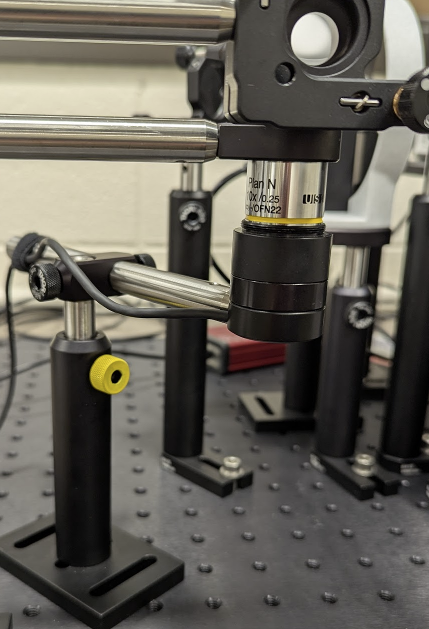
Figure 6: Microscope objective closeup Click the “Start Power Measurement” button.
The software will automatically take the measurement, and will plot measurements as it takes them.
After the measurement is complete, a window will appear asking you to save the data file. The filename should be set as:
YYYY_MM_DD_power_cell#.csv— save the file in an appropriate location.Verify that the power measurement plot looks like you expect. If you are not sure if your data are as expected, ask your TA to take a look.
Move the CSV file to your team’s Google Drive folder.
Loosen the yellow thumb screw on the post holder, lower the power sensor, and slide power sensor out from under the microscope objective.
Screw the cap back on the power sensor.
Make sure your power measurement data has been moved to your team Google Drive folder and then you can move on to the current measurements for your pixels.
4.2 Current Measurements
- The monochromator should be configured so that there is green light coming out of the microscope objective. If not, click on the “Align” button in the top-right corner of the app.
- You can use the green dot to align a pixel to the light. Click on the Live Monitor button in the lower-right corner of the app. Move the breakout box around slightly and watch the live monitor reading in the STATUS box. You can use this measurement to confirm if the photocurrent is being detected.
- Once you have found the appropriate position for the light on your pixel, click on the Stop Monitor button. Be careful not to bump the hot plate assembly during the measurement in the following steps.
- Click the Start Current Measurement button. A pop-up window will appear for you to specify which pixel number you want to measure. Type the appropriate number and click Start. You will notice that the Pixel number will now be updated in the top-right corner of the app.
- If any error or warning messages appear, be sure to notify your TA immediately. The software will then automatically take the current measurement and will plot measurements as it takes them.
- Verify that the current measurement looks like you expect. If you are not sure if your data are as expected, ask your TA to take a look.
- Record the time of the measurement for each pixel and input the time between when the cell was taken off the stressing station and the measurement was taken. (See lab guide for more information.)
- After the measurement is complete, a window will appear asking you to save the data file. The filename should be set as:
YYYY_MM_DD_current_cell#_pixel#.csv— save the file in an appropriate location. - Move the CSV file to your team’s Google Drive folder.
- Move the black lead to the banana socket connector of the next pixel you are measuring (e.g., 1 → 2).
- Align the green light to the next pixel, making sure to use the Live Monitor to validate alignment, and repeat the Current Measurements steps above until you have current measurements for the remaining pixels.
5 Experiment Wrap-up
This portion of the guide covers the steps for completing your EQE measurements and resetting the apparatus for the next group.
- Move the hot plate out from under the microscope objective.
- Close the “PHYS 2150 Measurement Suite” user interface. If you do not, the next group will not be able to take their measurements.
- Make sure all of your measurements are in your team’s Google Drive folder. Log out of the laptop.
- Unplug the 25-pin connector from your cell and open the lid. Remove your cell from the hot plate.
- Take your cell back to its stressor spot. If you have not yet taken your J-V measurements for the week, your cell will stay on the stressor until it is your turn.